Thursday, April 5, 2012

Rendering foliage with highpass filter

If rendering foliage on has two options:
  1. Render it in opaque pass, using alpha test to discard transparent pixels
  2. Render it in transparent pass, using true alpha blending
Alpha blending gives the best results but kills your rendering performance very quickly. First - the blending itself is much more fillrate intensive operation than opaque rendering. Second - you cannot use deferred rendering. And third - you have to sort polygons.

Here is the transparent pass render of small test scene, as a reference:

A patch of Dactylis glomerata, rendered in transparent pass

Even small patch of forest or meadow will have tens of thousands of polygons. Something like realistic landscape simply is not doable using transparency on current generation hardware.


This leaves us with the other option - opaque rendering.


While writing foliage shaders for Shinya the biggest problem was, that scaled down textures (i.e. higher mipmap levels) looked totally crappy. Whatever was the original shape of plant - looking at it from distance it morphed into rounded blob.
The reason for it was the minimization algorithm, that averaged alpha. Thus the parts of foliage where there were only few "holes" - i.e. central parts - became completely opaque. And the parts, where there were only few leaves - i.e. outer regions - became fully transparent.

The "original" opaque render, using default mipmap generation (box filer):

The same image, rendered in opaque pass with box-filtered mipmaps

While messing with textures and trying to find the best alpha cutoff value, I finally got the right idea - we do not want to get the average image but want to preserve "features" of image in minimization. Features being both "holes" and "patches" (i.e. leaves). This can be done by increasing high frequencies of image. I.e. we want to replace the standard mipmap generation filter (normally box filter) with something better.
Fortunately I was already composing mipmaps by hand while creating packed textures. Thus I added very simple edge-detection filter with 3x3 kernel to the foliage mipmap generation (after the minimization with box filer). And the results were really good.

The "enhanced" opaque render with edge detection filter:

The same image, rendered in opaque pass with edge-detection filter

As you can see, edge detection successfully preserves the general features of the texture - stems and narrow leaves, while simple box filter tends to smear these out.

The kernel for edge-detection was:

-1 -1 -1
-1  9 -1
-1 -1 -1

And here is a screenshot of the foliage shader in action. The meadow size is about 40x40 meters, grass is about 50000 instanced polygons.

Sara in meadow


You can download the Dactylis glomerata texture from my DeviantArt gallery.

Have fun!

Saturday, March 31, 2012

Shinya technology demo

Things are going pretty well in Shinya-land recently. For the first time it has materialized in the tangible form for people other than me. And got its own webpage as well: http://lauris.kaplinski.com/shinya/index.html.
You can find the technology demo at the download section in Shinya homepage.

Sara and wolf. Sorry - I don't have red riding hood model for her...

Some notes:
  • It is currently only for Windows. When I'll find time and there is interest, I'll probably try to release Linux version as well.
  • It is compiled in Windows 7 with VS2010 express - I hope that all dll-s are included.
  • It is alpha quality code - do not be surprised if it crashes or does not work at all.
  • It uses OpenGL - id it does not work, you may try upgrading graphic card drivers from NVidia or ATI.
  • Very little of the actual game-land is present yet. Or more precisely - the land is present, but mostly empty.
  • Movement and collision system is not fully finished yet.
  • Vladimir is liar - the town is called Spielburg, not Midgard.
  • You cannot initiate talk with wolf.

Have fun!
Lauris Kaplinski

Monday, February 13, 2012

Shinya - the game

I have made too big progress with Shinya to not share it at last...

It uses the same rendering engine as Khayyam (Sehle library). Most new (and unreleased) features in Khayyam are actually implemented so it can be used as scene builder for Shinya. Among other things there are now reflections, occlusion queries, volumetric lights and darkness, instanced vegetation, layered terrain and so on...
No - I have not forgotten the new Khayyam release. The main problem holding me back is that there should be at least preliminary support for new materials for POVRay exporter. And things just progress too fast...

Shinya playable tech-demo is nearly complete. The biggest roadblock at moment is fixing remaining shader bugs for ATI GPU-s (this is the unfortunate consequence of writing engine in OpenGL...)

OK, I know - pics or it did not happen...

Sara looking down to Shinya world

Shinya will be adventure game, similar in style to Quest for Glory series. It takes place in (alternate and fictional) medieval times somewhere in central Europe.

There is a bit more vegetation in some areas
The main heroine is Sara - a bit complicated 12 years old girl, who is recently moved to the area with her aunt (she is orphan, as expected).

Another human being!
She will involuntarily dragged into some intrigues, conflicts and mysteries that have lately developed in this otherwise tranquil place. Or maybe not so involuntarily - se is, after all, a bit complicated damsel...

A mill at the main river
Modeling in Blender has been the other big time-consumer other than programming. I am slowly starting to get a grasp of this program - not a pro yet, of course.
The most complex model so far is cathedral - LOD 0 is about 190 000 triangles (LOD 1 about 2500). I develop Shinya mostly on laptop with NVidia GT540M GPU - and thus hope, that for the time it will be released it runs smoothy on most desktop computers at least.

Inside cathedral
The world of Shinya is 4x4 km freely roamable terrain. It has continuous day/night cycles - but you cannot stay awake indefinitely, even by using stamina potions. Thus NPC-s will have certain time to arrange things without player peeking over their shoulders.

Ah, almost forgot - Shinya it is written 深夜

Have fun!

Tuesday, January 17, 2012

Models and textures

I have been busy with modeling and texturing for Shinya - and rewriting parts of Khayyam/Sehle to support certain must-be features like vegetation instancing and geometry LODs. Some (semi)finished things are available for download - more will come. Although certain parts will probably remain secret fro now...

Models

Sara the tween girl (Blender render)

Textured and rigged, about 6000 polygons. Blender source file and some exported formats can be downloaded from TurboSquid.

Oak tree (Blender render)
Oak tree with 3 LOD levels.
  • LOD0: 4407 vertices, 2791 faces
  • LOD1: 645 vertices, 442 faces
  • LOD2: 21 vertices, 7 faces
  • Collision (only trunk): 24 vertices, 16 faces
Blender source file can be downloaded from OpenGameArt.


Unfinished medieval house. About 10000 polygons, needs some agressive LODing.

Cathedral interior (Blender render)
Unfinished cathedral. About 55000 polygons - half of those are window frames. Needs also some agressive LODing to be usable in game.

Textures

Seamless ground texture - dead leaves

Small collection of plant and ground textures is available from my DeviantArt page.

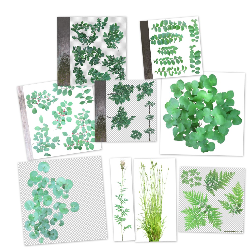
Cut-out plants

A collection of cut-out plants at OpenGameArt.

Have fun!

Saturday, December 17, 2011

Matching image colors with Texturewerke

In the last post I demonstrated how to use TextureWerke for masked polynome high-pass filtering. In addition to that, TextureWerke 0.1 has another feature - matching colors between two (masked) images.

Workflow

Let's start with two images of stone wall we want to merge into one texture:

First image - a plain wall

Second image - a corner made of bricks

As you can see (among other things) the images have a bit different colors - the first one has more contrast and red. The bright background of the second picture influenced camera color adjustment logic so that the wall is more gray and has less contrast.
We will correct this automatically. First we move both photos to the same image (not necessary, but easier to compare) and add masks. We mask out all details that we do not want to influence final color - i.e. roof, shaded areas, brick structures, grass and background.

Masked images on top to each other.

Next we select the masked layer whose colors we want to change (Layer 2), invoke TextureWerke and choose color matching mode.

TextureWerke dialog window in color mode

Template is the (masked) layer whose color profile we want to emulate in selected layer.
Blurring reduces the noisiness of distribution curves and thus helps to overcome artefacts resulting from different sharpness of images. On the other hand it may mask out certain differences in color distribution and thus reduce the matching quality. You can always try and use what gives the best results.
And at last we apply the filter.

Image with adjusted colors

As you can see, the overall color and contrast of the (stone part of) wall matches with template image. On the other hand the areas that were masked out (bricks, backround...) are now completely off. But probably we did not want to use these anyways - except bricks maybe - but these can easily be copied and pasted from the original, and adjusted separately.

FYI: Internally the algorithm works by comparing pairwise the cumulative distributions of each image channel (R,G,B,A) and building a transfer function that translates the values with one distribution to the values with another (template) distribution.

And that's all. Have fun!

Thursday, December 8, 2011

Texturewerke 0.1

While doing textures for Shinya (the game with Khayyam/Sehle engine) I got frustrated with GIMP built-in tools and plug-ins available for texturing and decided to write my own tool Texturewerke. The initial version is now available for download from SourceForge:
At moment it can do two things:
  1. Adjust the colors of one (masked) image so it matches as well as possible with another. Thus you do not have to manually adjust color curves to merge several photographs into the same texture.
  2. Filter out low frequencies from image (while keeping the average intact). This can be used both for the creation of seamless textures and for removing shade gradient from uniform surfaces (like walls, doors, whiteboards...) Highpass filter supports masking (in polynome mode), so you can mask out those details whose contribution you want to ignore (like pictures on wall).
Below is one possible usage scenario of Texturewerke highpass filter.

Polynomic highpass filter with masking

We want to use the following image as a texture. Unfortunately the background color is non-uniform and adjusting it by hand is boring work

The original image - notice the non-uniform shading of the wall
We select the are that we want to have uniform color (the wall). It does not have to be precise - the filter samples few thousand points from target area and thus small regions of wrong color do not disturb the result much.
In given case I used magic want to select white and then added and subtracted few rectangles.

Target region selected
Now we turn target region into mask, bu choosing "Add Layer Mask" from Layer menu.

Target region turned into mask
Next we invoke Texturewerke plugin and select "Lowpass" filter and "Polynome" mode.

The Texturewerke dialog window
It blurs image (internally) before calculating polynome approximation. The optimal size of kernel depends on image and the number of samples used. As general rule - the more samples it uses, the smaller can be the kernel.
Next we apply filter.

Masked image after applying polynome filter
As you can see, the unmasked area has almost uniform color/bightness now.
As the last thing, we delete (or turn off layer mask).


The final image - wall color is now uniform
 And the final image has now nice uniform wall color.

There are few things to notice:
  • Polynome mode tries to approximate the average color of the image by two-dimensional polynome (up to 4th degree). The approximation process guarantees the correct behavior of the polynome only inside target region - the higher is its degree the faster it goes "wild" outside. Thus if you mask out some edges of the image the results probably will not look nice for anything above quadratic (2th order).
  • The unmasked area has to be at least 10% of original image
  • Samples are drawn randomly from unmasked area.
  • There is another highpass filter mode "blur", that subtracts blurred (lowpass) version of the same image. It does not support masking - but it may be more useful for the generation of highly uniform images (like grass and sand textures).

Have fun!

Tuesday, October 4, 2011

Reflective water with GLSL, Part II

In the first part I explained how to implement a basic reflective surface. But as we could see, it was very poor approximation of true water, looking more like mirror lying on the ground.  First because real water is almost never completely still. But it is also not perfect mirror - depending on viewing angle we can see more or less into the water.
Before going to implementing ripples I'll show how to adjust water shaders so the angle-dependency of reflection strength is taken into account. And being already there, how to fake the light attenuation/scattering in water so it is not crystal-clear but has more realistic color.

1. The relation of reflectivity and viewing angle

If you imagine looking at water body from different angles it should be obvious, that the lower is viewing angle the more light it reflects. Sea may look almost like perfect mirror during tranquil sunset - but if you are looking daytime from the top of a cliff, you can see the blueish-greenish color of water and only a little reflection.

The reflectivity of water comes from the difference in refractive indexes of air and water. As the speed of light is different in these mediums, some light is reflected and the light entering water changes slightly its direction - the latter is called refraction. Refraction is another phenomenon that can add realism, but we will not try to simulate it here.

A schematic diagram of reflection and refraction

Mathematically the amount of light reflected from the surface of water is described by Fresnel equations:

Fresnel reflection equations (source Wikipedia)

Rs and Rt are the reflectance values of vertically and horizontally polarized light.
θi and θt are the angles between the surface normal and incident and refracted rays.
n1 and n2 are the refractive indices of two media - in our case air and water. The relevant values are:

n1 = 1.000277 ≈ 1
n2 = 1.3330

We do not need θt because it can be derived from θi and refractive indices using Snell's law - look at the rightmost part of equations.
The reflectance values are different for differently polarized light. This explains the magic behind anti-glare sunglasses and optical filters - they cut off vertically polarized light, that is much more strongly reflected.
It is also interesting to know that skylight is in fact somewhat polarized. But for our simulation we ignore this and treat all light as the uniform mix of both polarizations. In that case, the total reflectance can be simply calculated as:

R = (Rs + Rt) / 2

The full Fresnel equation above is a bit too complex for our shaders. It is physically correct - but our goal is natural or good-looking scene and we are ready to sacrify a little here ad there to save shader instructions for other things.
There is quite simple approximation available. Take a look at the following graph:

Fresnel reflectance values Rs, Rp and R (blue, red, yellow) and our approximation (green) 
The green line represents function:

R = Rmin + (1 - Rmin) * (1- cos θi)5

That can be used as good approximation.
Rmin is 0.02 for real water, but you may want to increase it to something like 0.1 or even more, unless you have very good HDR implementation. The problem is that real sky is really bright - if you are using dimmed down version of sky, its reflection is not visible at all from high angles.

That's it. Now we have reflectance value calculated - but we cannot yet update our shaders. Unlike in our previous lesson, where the reflection was all that had to be rendered, we now have to render the water itself too - unless the reflectance is exactly 1.

2. Rendering water

Water is normally dense medium and strongly scatters light. The actual formula is quite complex and depends on the amount of different chemical compounds (such as oxygen, humic acids) and various inorganic (such as clay) and organic (like plankton) particles in water. But our goal is not to simulate procedurally the color and turbidity of water, but instead find a meaningful set of descriptive parameters, that will give us good enough approximation.

Scattering changes the intensity of light (ray) in two ways:
  • Out-scattering - if ray of light goes through medium, some fraction of light is scattered away from direct path and thus the final amount of light is lower.
  • In-scattering - as light is scattered to all directions, some light from rays originally going other directions is scattered to the direction of the ray of interest.
Because of out-scattering the bottom of deep water body is dark. Because of in-scattering objects inside water seem "tinted" with water color.

Scattering in water. A - in-scattering. B - out-scattering.
In addition to scattering there is one more phenomenon causing less light to come from water - it is internal reflection. As light hits the bottom of water body or objects inside it and goes upwards from there, some of it is mirrored back into water from the air-water phase surface.
We ignore this at moment and will use shortcut - instead of adding together the light coming from inside water and light from reflection, we draw the latter as semitransparent surface using reflectance as alpha value. Thus the higher is reflectance, the lower is the effect of light from inside water - which is generally correct, because the internal and external reflectance values are correlated.

How good our water formula can be depends on whether we can read the color and depth values of the bottom of water body or underwater objects in shader or not. Here I present a simple approach, that does not use them, but instead adds the color of water to the reflection image.

We ignore the exact scattering equations, that involve multiple integrals and instead combine the "tint" of water with the color of reflection (that is semitransparent now) and then render them as semitransparent surface over the already rendered bottom of water. For this I use a very simple formula:

Ctint = Cwater * (Omin + (1 - Omin) * sqrt (min (thickness / Dopaque, 1)))

Ctint is the color that water adds to objects (premultiplied)
Cwater is the color of opaque water column
Omin is the minimal opacity of water. It should be 0 for realistic simulation, but in reality values 0.1-0.2 give overall better effect.
Dopaque is the depth of water column, that becomes fully opaque. The reasonable value is 2 m for freshwater bodies - the smaller the better, as it helps to hide the lack of refraction.
thickness is the thickness of water in given direction until bottom or some underwater object is hit.

Calculating thickness is tricky. The technically correct way would be to trace ray in refracted direction until bottom (line AC in following figure) - but we cannot afford to do that.
If you can use depth buffer, you can ignore refraction and calculate the distance the original ray would cover underwater (line AD). This overestimates the thickness, but as the effect only becomes noticeable at low viewing angle, where reflection dominates, it should look quite good.
Here I will use even simpler approximation. Just find the depth of water under given point of surface (point B on following figure), and pretend that water has uniform depth (line AB1). It underestimates depth at the slopes directed away from viewer and overestimates at slopes directed to viewer, but if the bottom of water is reasonably smooth it is not too bad.

A diagram of different possible methods for water thickness calculation
How to get the actual water depth under given point?
Recall the previous tutorial. We set the Z coordinate of vertex to 0 (i.e. flatten our object), but kept the full original vertex coordinate in interpolatedVertexDepth.
Thus if the object being rendered as water is actually the bottom of water body, it will render as flat surface, but we have access to the original Z coordinate of it. In other words - the water depth.
Another approach would be to encode water depth into another vertex attribute. It has some good points - like no need to separate the bottom of water body from other terrain and the possibility to hand-code depth.

Once we have calculated water thickness with whatever method applicable, we treat the tint color as another semitransparent layer, lying directly beneath the reflection layer. The final color and alpha values can be calculated by standard alpha blending formula:

C = Areflection * Creflection + (1 - Areflection) * Cwater
A = Areflection + (1 - Areflection) * Awater

Where C and A are color and alpha values.
If the resulting alpha is below 1, bottom or underwater objects are partially visible.

3. Shaders

There is no need to change vertex shader.

Fragment shader:

uniform mat4 o2v_projection_reflection;
uniform sampler2D reflection_sampler;
uniform vec3 eye_object;
uniform float min_opacity, opaque_depth, opaque_color;

varying vec3 interpolatedVertexObject;

void main()
{
    // Vertex on water surface
    vec3 surfaceVertex = vec3(interpolatedVertexObject.xy, 0.0);
    // Reflection angle
    vec3 vertex2Eye = normalize (eye_object - surfaceVertex );
    float cosT1 = vertex2Eye.z;
    // Reflectance
    float c = 1.0 - cosT1;
    float R = min_reflectivity + (1.0 - min_reflectivity) * c * c * c * c * c;

    // Water density
    float depth = -interpolatedVertexObject.z;
    float thickness = depth / max (cosT1, 0.01);
    float dWater = min_opacity + (1.0 - min_opacity) * sqrt (min (thickness / opaque_depth, 1.0));
    // Premultiply
    vec3 waterColor = opaque_color * dWater;

    vec4 vClipReflection = o2v_projection_reflection * vec4(interpolatedVertexObject , 1.0);
    vec2 vDeviceReflection = vClipReflection.st / vClipReflection.q;
    vec2 vTextureReflection = vec2(0.5, 0.5) + 0.5 * vDeviceReflection;

    vec4 reflectionTextureColor = texture2D (reflection_sampler, vTextureReflection);
    // Framebuffer reflection can have alpha > 1
    reflectionTextureColor.a = 1.0;

    // Combine colors
    vec3 color = (1.0 - R) * waterColor + R * reflectionTextureColor.rgb;
    float alpha = R + (1.0 - R) * dWater;

    gl_FragColor = vec4(color, alpha);}

We have added another uniform (in addition to water color and opacity ones) - eye_object, that is simply camera position relative to water object local coordinate system.

And real-time image from Shinya:

Simple scene from Shinya with partial reflection and water opacity 

Now it is a bit better than last time - but still artificial and lifeless. Next time I show, how to make it live - i.e. add waves or ripples.

Part 1 - reflective surface

Have fun!